Doing Designs for Learning Purposes
Matrix (or Grid) switchers have fascinated me since I was a kid. You have a panel full of holes, inputs up the left, outputs along the top. (Or right and bottom, or both.) By sticking a pin, or shorted jack plug or throwing a switch, you can parallel, mix, match and repatch a synth or a mixing desk, etc, almost any way you want it configured. A friend in senior secondary school built an ETI 5600 from discrete parts and the pin-patchbay amazed me!
Anyway, cut to the 21st century, and I want one that's logic controlled. And flexible. Like a Lego matrix switcher. I have a Zoom L-12 mixer/recorder and the monitor busses seem to me to be just perfect for mix groups. With this I want a switcher that can select my regular mic and instrument inputs and patch them through to my 12 lin-ins, or select my B, C, D and E monitor outs (via appropriate headphone to line matching), to give my studio greater flexibility. I could make a matrix switcher out of SPDT toggle switches, but that'd be very 20th century. I want it Arduino controlled. And I want to be able to build various versions of it. Any number of inputs to any number of outputs, one 2x2 board and one Arduino Nano, with an extra Nano to rule them all. Initially 6 in, 12 out. See what I mean by Lego for patching switchers?

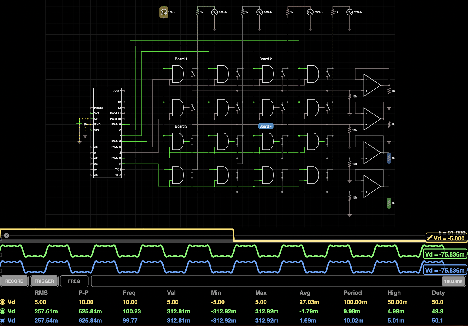
This is the circuit board the schematic above references as "board 1", "board 2", etc. The board uses a CMOS CD4011 quad AND gate to operate a CD4066 quad bidirectional switch at each node of the matrix. Two input-select control signals and two output select control signals drive the inputs of the AND gates, which each have an input and an output signal on them. If an AND gate has one of each, its output "lights up" and turns on the switch at that point in the matrix, connecting the selected audio input to the selected audio output, allong the signal to pass. Where one or both of the inputs on an AND gate is low, a signal can't flow through the switch at that point. Where both inputs are high, the switch closes and the audio signal flows through from input to output.
In the circuit diagram, I've tested the signal paths by placing a fundamental signal of 100Hz and 3 odd harmonic signals of 300Hz, 500Hz and 700Hz, each of an amplitude in inverse proportion to their frequencies, 1v, 1/3v, 1/5v and 1/7, respectively. The 4 sine waves mixed approximate a square wave. Tube v Transistor amp theory. By changing the output states on the Arduino, I can show by the changing waveforms whether an input or output is on.

The prototype circuit board, 2 ins and 2 outs, can be arrayed to create a logic controlled patchbay as large or small as you like. The boards are 60mm wide by 50mm high, so take up very little room, are drilled, so the arrays can be stacked with threaded rod and spacers. 4 to 9 boards could easily be controlled by an Arduino Mega 2560, or each board could be controlled by an Arduino Nano, operating as an I2C slave, in turn controlled by a Nano as the I2C master. This is the board at actual size, at 72dpi resolution.
You could build a switcher like this using a square of Make-A-Bracket and up to 80 SPDT toggle switches, but you wouldn't be able to store different patches for different signal paths. There are advantages and disadvantages to each method. The cost of the chips and circuit boards are less than double the cost of a submini SPDT switch. I plan to try designing 2 (maybe 4) of these and a "Mega2560 mini" into a Eurorack module form factor. Hope you Eurorack, Electropop peeps appreciate the thought 🤣 ❤
The parts list consists of a CD4066 quad bilateral switch and a CD4011 quad AND gate, that's it. In Fritzing I used 2.54mm generic headers as my drill spacing, but just solder wires to hook it all up. It should even be relatively noise free, even on veroboard. The zipped Gerber file for the board is here and the Fritzing project file (also zipped) is here.
In the circuit diagram, at the top, I do show op-amp output buffers, but I'd add those in on a project-by-project basis, on a separate board, which I may design and post here, or not. Yeah, I use iCircuit for my simulations, so I usually go straight to the PCB stage. The circuit diagram and breadboard in the Fritzing file are a mess. Feel free to fix them if you don't use a circuit sim, like I do. Nearly cuts out the need for breadboarding altogether. Nearly...
I may do a slightly larger 4x4 board, with inbuilt Nano (I2C slave mode), four 4011 and four 4066 chips (4x4=16), too, maybe even with two LM358 op-amps. I want to keep the board small, though, that's still an important factor. As much as possible, guitar pedals in a 66x120 box and, if a project goes to a rack, single RU, as much as possible! This will be for my L-12 rig, three of the slave boards and a master/interface/control/display board. When/if I get to that project, I'll begin sharing the firmware, once I've got a working basic model happening.
All of my designs are maked with copyright dates, but I support copyleft and open source. The general rule is, you can make anything I post, and improve on it, provided you attribute the original work to me, share-alike (as in by these rules, right here, and by Creative Commons) and generally non-commercial, unless you have negotiated a deal to pay me a "designer's share" of profits and are willing to open your books to me or my tax agent on request. Pay the artist, pay the designer, pay the technician. Everybody's art or skill has value, don't steal, stealing is punching down. This philosophy is very important to me as it's the basis of an anarcho-collectivist economic model. The model I followed playing in most of the bands I was in.
Chears,
Crunchy.


Comments
Post a Comment